Hotest Articles


Thanks to a wide range of machines and materials, CNC machining is capable of creating a vast array of professional parts for use in many industries. However, engineers must be careful to design parts in a way that suits the manufacturing process.
Considering the possibilities and limitations of the CNC machine — whether it’s a mill, a lathe or a high-end 5-axis machining center — leads to better parts, even if compromises have to be reached. A part is both enabled and constrained by its manufacturing process.
With that in mind, designing for manufacturability, by following certain design principles, ensures that parts will come out in the best way possible, will not break during machining, will not damage the machine itself, and will be fabricated in an efficient and cost-effective manner.
This section of the GUAN SHENG Knowledge Base looks at how parts can be designed in an optimal way for CNC machining.
Initial considerations
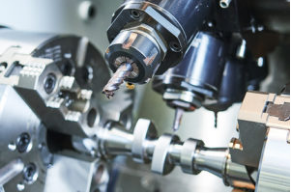
When designing a part for CNC machining, the first question one must ask is: what kind of CNC machine will be used for the part? GUAN SHENG uses a variety of machines, including standard mills, lathes and 5-axis machining centers, and these different machines are capable of creating different kinds of CNC machined part.
Let’s look at a standard 3-axis vertical machining center as an example. When designing a part for 3-axis machining, one must consider the function of the machine: the cutting tool moves along three axes but always faces downwards, which naturally limits the kind of cuts the machine can make in the workpiece. If you create a diagonal cavity on the underside of the part, the machine will not be able to cut it unless the part is completely reoriented.
This is one of the most important factors to consider when designing CNC parts. If cuts need to be made on the reverse side of the part, the workpiece must be set up again the other way round. If it needs to be cut at a diagonal angle, it must be set up once more. These multiple setups take time and ultimately cost money, and it is therefore beneficial to design parts with features that face the same direction, reducing setup time.
5-axis machining centers, on the other hand, can cut the workpiece from a much greater number of angles, which therefore increases the engineer’s design freedom.
The cutting tool itself must also be considered. The cutting tool of a CNC mill, for example, has a cylindrical shape, and therefore cannot cut perfect right angles into a workpiece.
Specific considerations
Tolerances
Tolerances let the manufacturer know how closely a part’s dimensions must match those specified in the design or technical drawing. Tighter tolerances mean the dimensions must be almost exact, while looser tolerances indicate that speed and cost are more important than micrometer-level accuracy.
Most CNC machines can achieve fairly tight tolerances (± 0.025 mm is standard), but ultra-tight tolerances require more labour and are therefore more expensive.
Remember that not all part dimensions demand the tightest tolerances. If a part does not form part of a mechanical system, for example, a matter of micrometers may make little difference to the part’s function. Prototypes, too, can often be CNC machined with fairly loose tolerances, which can then be tightened up for the final part if necessary.
Cavities
Many CNC machined parts incorporate cavities for mechanical or fitting reasons, or to reduce mass. However, the dimensions of the machine’s cutting tool determine how deep these cavities can go.
In general, a machined cavity should be no deeper than four times the width of the cavity. This helps to avoid tool deflection and prevents chips getting stuck in the cavity and causing problems.
Wall thickness
Although CNC machines can make very fine cuts in the workpiece, machining very thin walls can result in a lack of stability. When machining plastic, very thin walls can easily deform, so it is often best to keep walls a reasonable thickness.
How thin these walls can go ultimately depends on the machine and material used. Metals are more resilient, and can — at a stretch — go as thin half a millimeter. Walls machined from plastics, on the other hand, should be around twice that thickness at a minimum.
Threads
CNC machined parts often have threads for screws or other fasteners, so that multiple parts may be attached together. Unlike 3D printed parts, for example, machined parts are highly amenable to threads, since there are cutting tools made specifically for them.
These thread mills can create a highly accurate thread in either plastic or metal, but are not the only way to create threads. Other tools for creating threads include cut taps and form taps.
As with holes and cavities, threads made using taps should only go so deep into the machined part.
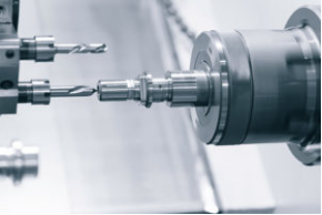
Holes
Machined parts can incorporate round holes, which are created using a drill bit or end mill. There are limits to the depths of these holes: more than ten times the diameter becomes more difficult and may contribute to a higher cost.
In general, end mills create holes with a better surface finish and offer greater flexibility in terms of hole size. They are, however, limited in length.
Text
Adding text to a machined part is a surefire way of making it identifiable or brand-specific. It is also a surefire way of increasing cost, and is therefore considered something of a luxury for functional parts.
Recessed text is faster and cheaper to write than raised text, and each character should be at least half a millimeter apart to avoid deformation. Fonts should always be sans serif, without unnecessary embellishments. (Remember: text does not need to be added using machine tools; it can be painted or added to a sticker.)
Designing undercuts for CNC machining
Because many common CNC machines — 3-axis milling machines, for example — can only cut downwards, any features that are inaccessible to the downward-facing cutting tool cannot be cut in the normal way. These inaccessible features are known as undercuts.
If possible, undercuts should be avoided altogether. However, when they must be included in the part design, there are a few rules to follow to ensure proper part fabrication.
Undercuts come in two main varieties: T-slots and dovetails.
T-slots are horizontal cuts, and T-slot cutting tools therefore utilize horizontal cutting blades fitted to a standard vertical spindle. This allows for a standard 3-axis machine to cut sideways instead of downward, allowing the machine to create horizontal undercuts.
Dovetail undercuts involve diagonal angles. To create a dovetail undercut, a dovetail tool with a conical surface is used, and these tools are most commonly found with 45° or 60° angles.
In general, 5-axis machining centers are much more capable of creating undercuts, since they can automatically rotate the spindle or workpiece to find a suitable angle for a pass. If designing a part for 4-axis or 5-axis machining, it is rarely necessary to avoid or minimize undercuts.
Checklist
Has the part been designed with a particular CNC machine in mind?
Have suitable tolerances been specified?
Have hole depths been minimized?
Are walls suitably thick?
Is text in a sans serif font with adequate character spacing? Is it necessary?
Have setups been reduced by aligning features in consistent directions?
Can undercuts be minimized or eliminated?