Hotest Articles


Injection Molding
The Concept of Plastics and Material Classification
Injection Molding: Introduction
Injection Molded Parts: Design Considerations
Introduction to Injection Molding Machine
Mold: Introduction
Injection Molding: Material Characteristics (taking POM as an example)
Injection Molding Process: Parameters
Plastic Defects (forming defects and countermeasures)
1. The Concept of Plastics and Material Classification
Definition of Plastic
Plastic- It is a polymer material that is made of resin as the main component, it may be with or without the addition of other compounding materials (auxiliaries), and it can be molded under heat and pressure.
Source of Plastic
The basic raw materials for plastics are carbon and hydrogen compounds of low molecular weight. The main sources of synthetic plastics include natural materials such as crude oil, natural gas, coal, salt etc.
Classification of Plastic materials according to their basic performance

General Purpose Plastics: Polyethylene (PE), Polypropylene (PP), Polystyrene (PS), Polyvinyl Chloride (PVC), ABS etc.
Features: This category of plastics have a large output, low price and are usually high on general performance

Engineering Plastics: Polyamide (PA), Polycarbonate (PC), Polyoxymethylene, Polyphenylene Ether
Features: It has excellent mechanical properties, electrical properties, chemical properties, heat resistance, wear resistance and dimensional stability. Production of engineering plastics is relatively small and so, the price is expensive.
Functional Plastic: Medical plastic, Photosensitive plastic
Features: This type of plastic has special functions.
Classification of Plastic materials according to heat
Thermoset Plastic: In this type of plastic, a soft solid or viscous resin is irreversibly hardened by curing over a specified temperature range. Such plastics are basically made using the material (resin) obtained by the polymer reaction and do not cause chemical cross-linking when heated. Thus, it is still malleable even when it is heated again. These types of plastics include polyethylene, polypropylene, polystyrene, polycarbonate, etc.
Thermoplastic: It is a kind of plastic that can pliable when heated above specific temperature and hardens when it cools. This type of plastic is basically made of a resin obtained by a polycondensation reaction, which is a chemical compound which undergoes a chemical change upon heating and this causes a linear molecular structure resin to be converted into a bulk structure of a polymer compound. When heated again, it no longer has plasticity, and this category includes plastics such as Phenolic plastics and Aminoplast.
Classification of plastic materials according to molecular heating characteristics
Classification of thermoplastics not finalized:
Advanced Engineering Plastics: It includes FluoroResin, Teflon, Tefzel, PSU, PES, PPSU etc.
Engineering plastics: It includes Polycarbonate, PPO etc.
General Purpose Plastic: It includes ABS, PVC, PMMA, Polystyrene, SAN etc.
Crystallinity:
Advanced Engineering Plastics: It includes Polyurethane, PTFE, Liquid-crystal Polymer (LCP)- Zenite, High-temperature Nylon (HTN)- Zytel etc.
Engineering Plastics: It includes PA nylon (Zytel & Minlon), polyformaldehyde (POM) (Delrin), PBT (crastin & rynite), PET, TPE (Hytrel- Polyester Elastomer) etc.
General Plastic: It includes PP-GF, PE-UHMW, PP, PE-LD, PE-HD etc.
The difference between Amorphous plastics and Crystalline plastics:
Injection molding cycle and types of plastics
The two major types of plastics used in the injection molding process are:
-Amorphous Plastics, and
-Crystalline Plastics.
The injection molding cycle includes:
-Fill time
The filling time corresponding to the minimum injection pressure is required to fill the mold.
-Clamping
The two halves of the injection molding unit are closed by a clamping unit before the mold is injected with material
-Injection
The resin is fed into pellet forms by a hopper into the injection molding machine. The time for the injection process is estimated by other factors like power and shot volume, injection pressure and machine type.
-Cooling
The plastic inside the mold is cooled down after it is molded. As the plastic cools down, it takes the desired shape.
-Ejection
This is the last stage of the injection molding cycle where the final part is pushed out of the mold.

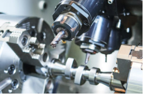
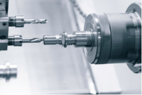
2. Injection Molding: Introduction
In the method of Injection molding, the granular or powdered plastic is placed in the barrel of the injection machine to be heated, and after being melted, the pressure is applied by the push rod or the rotary screw, in a way that the rubber in the barrel is injected from the nozzle and the casting system of the mold to the mold type. This material is then cooled in a cavity.
The overall structure of Injection molding includes:
Photometric Stereo vision technique
Injection part
Electrical control section
Body part
Mold part
Lubrication part
Security door
Hydraulic transmission part
3. Injection Molded Parts: Design Considerations
1. Two basic requirements for mold design of injection molded parts are:
Reasonable structural design
Usable structural design
The Mold forming part cavity should be open so that the molded part can be taken out easily
Note: The mold design should be as simple as possible (the mold movement should be as small as possible)
2. The importance of uniform wall thickness in injection molded parts
With wall thickness changes there can be a sudden change in direction and flow rate of molding which can cause defects like sink marks and flow lines. If the molding process is done with the wrong gate, it is almost impossible to correct the resulting consequences during the forming process. Also, regardless of the position of the mold gate, it is possible to cause poor molding.
The design of the injection molded parts should be properly considered as rounded corners in the design of the mold ensures even wall thickness that improves the flow of the melt around a corner and also increases the strength of the molded part. Plastic parts should be considered for uniform wall thickness when designing injection molded parts. Ribs can be used to improve the wall thickness of plastic parts and their durability as well. The uniform wall thickness of a mold vastly affects its structural design.
3. Mold strength
Mold strength should also be considered when designing injection molded parts as plastic structure designs with elongated slots, designs with elongated round holes offer better strength than plastic structure designs with sharp corners.
4. Simplification of the mold design
It should be considered when designing the injection molded parts (reducing the mold movement) as simplified mold designs like Side mold cored plastic structure designs or Plastic structure designs with sharp corners are easy to produce.

5. Reasonable design of Ribs
In plastic design, the cross structure is the best because it can handle many different load arrangement changes. A properly designed cross structure that can withstand the expected stress ensures a uniform distribution of stress across the article. The nodes formed at the intersection represent the accumulation of material, but the center of the node can be hollowed out to prevent problems. It must also be noted that material accumulation does not occur where the intersection intersects the edges of the component.3.6.Reasonable design of the draft angle
The importance of the draft in Injection Molding is that it makes de-molding easy and prevents war page.
Remarks: For POM material it is recommended to use 0.5-degree draft
4. Introduction to Injection Molding Machines
Classification of Injection molding machines-
By structure:
1. Vertical injection molding machine
The injection molding plunger (or screw) of the injection molding machine is vertically disposed, and the moving template of the clamping device also moves in the vertical direction.
2. Horizontal injection molding machine
The injection molding plunger (or screw) of the injection molding machine and the mold clamping movement are installed horizontally, and most of them are in a straight line (or parallel to each other). It is currently the most widely used injection molding machine.
3. Angle injection molding machine
The injection molding plunger (or screw) of the injection molding machine is perpendicular to the mold clamping direction, and the large angle injection molding machine is filled with the plastic cylinder and the mold clamping motion is evenly arranged in a horizontal axis with the ground.
5. Mold: Introduction
Basically, an injection mold is a heat exchanger, a cooling fixture for the molded part that allows the thermoplastic to solidify into the desired shape and size in the cavity.
1. Mold classification:
Two-plate mold
The components of a two-plate mold include movable side mounting, backing plate, a support plate, movable side formwork, fixed side formwork, fixed side mounting plate, a positioning ring, runner bushing, guide bushing, guidepost, return lever, ejector bottom plate
Three-plate mold
The components of a three-plate mold include movable side mounting, backing plate, a support plate, movable side formwork, fixed side formwork, spore splitter plate, fixed side mounting plate, a positioning ring, runner, runner bushing, guide bushing, guidepost, return lever, Ejector bottom plate
2. Comparison of differences
Difference between two-plate mold and three-plate mold
3. Hot runner and Cold runner system for Injection Molding
The use of hot runner systems in plastic injection molding has been around for nearly 50 years now, but since the late 1990s that the use of a hot runner system has surpassed cold runner systems in plastic injection molding. The cold runner system is also called the Ordinary gating system.
It usually includes:
Hot runner gating system
The plastic that has not been injected into the cavity in the hot runner will remain in a molten state and will enter the cavity when filling the next plastic part, so it will not become a gate waste. Hot runner systems, also known as hot manifold systems or runner less molding, are commonly used in hot runner systems including:
Adiabatic
Heated (internal and external)
Hot runner system classification
Types of hot runner systems:
(a) Adiabatic,
(b) Internally heated, and
(c) Externally heated
The Advantages and Disadvantages of these hot runner types are:
Hot runner system heating principle
The Hot runner molds consist of two plates that are heated with a manifold system. This manifold helps in maintaining a consistent temperature by keeping the molten thermoplastic in the runners at the same temperature as the heating cylinder. The heated runners send the molten plastic to nozzles that fill the core mold to form the final part. The heated runner system is placed in a separate plate and this plate remains stationary during the molding cycle.
4. Gate- Introduction
The gate is directly connected to the plastic part and the plastic part is melted into the cavity. The gate is the key part of the gating system. The shape and size of the gate have a great influence on the plastic parts. In most cases, the gate is the smallest part of the entire channel system, which controls the filling flow.
Classification of gates
According to the shape of the fracture:
Round- Like Common needle gates, latent gates, and mainstream gate gates etc.;
Rectangle- Like Common edge gates, tab gates etc.;
Slit shape- Like Fan-shaped, film gates etc.;
Circular section: Like main runner gate, pinpoint gate, latent gate etc.;
Rectangular section: Like edge gate, tab gate, overlapping gate etc.;
Slit profile: Like fan gate, film gate, disc gate etc.
Gate design principle
1. Design the gate properly to spread the melted material evenly and in a single direction to fill the cavity and obtain a proper set time to cool the part.
2. The gate should be shot at a suitable location, such as a non-functional area or a non-appearance area.
3. The gate is placed in the thickest part of the plastic part, allowing the plastic to flow from the thick area to the thin area, which helps to obtain a good flow path and pressure maintaining path.
4. Place the gate in the center of the plastic part, so that the melt flow to the end of the plastic part has the same flow length.
5. The position of the gate must allow the gas in the cavity to escape during injection molding.
6. The position and size of the gate should also be designed to avoid jet flow.
7. The gates should well-designed gates as they prevent melt backflow.
8. Numerical simulation of injection molding is an effective tool for comparing the effects of different gate designs.
Gate design
Gates are vital in injection molding as they serve as the boundary between the part and the scrap, so its location, size, and shape play an important role in how everything should be constructed, from structural integrity to exterior appearance of the finished product.
The different types of Gate Designs are:
Direct Gate/Sprue gate
Pros:
1. Little pressure loss;
2. Easy preparation.
Cons:
1. High stress around the gate;
2. Gate scars can be left on the surface.
Side Gate:
Pros:
1. Easy processing, Simple structure;
2. Easier to remove the gate.
Cons:
1. Automatic separation of the part and the gate is not allowed;
2. Gate marks are easily left on the plastic part.
Tab Gate:
Pros:
1. It is a form evolved form of the side gate, so it shares the various advantages of the side gate;
2. It can prevent molten plastic jetting.
Cons:
1. Automatic separation of the part and the gate is not allowed;
2. Obvious gate scars are easily left on the surface.
Fan Gate:
Pros:
1. The horizontal distribution of the molten plastic is more uniform when passing through the gate, helpful for reduction of plastic part stress;
2. Lower the possibility of air getting into the cavity, to avoid the occurrence of defects, like silver lines and bubbles, etc.
Cons:
1. Automatic separation of the part and the gate is not allowed;
2. Long gate marks are left on the edge of the plastic part, which needs to be flattened by a tool.
Submarine Gate:
Pros:
1. Flexible choices of gate location;
Automatic separation of the part and the gate is allowed;
3. Smaller gate marks;
4. Applicable for both two-plate and three-plate molds.
Cons:
1. The plastic powder is easily dragged at the gate position;
2. Stress mark is easily created at water entry;
3. Plastic films need to be sheared manually;
4. Great pressure loss from the gate to the cavity.
Point Gate:
Pros:
1. Flexible choices of gate location;
2. Automatic separation of the part and the gate is allowed;
3. Smaller gate marks;
4. Low stress around the gate.
Cons:
1. High injection pressure;
2. Complicated structure, usually employing the 3-plate structure.
5. Molded parts
Molds can be of two types, male molds and female molds. With male molds, the thermoplastic sheet is placed over the mold and in female molds, the thermoplastic sheet is placed inside of the mold. Male molds are generally used when the inner dimension of the plastic part is a priority and Female molds are used when the part’s outer dimensions are more important than its inner dimensions.

1. Male Molds:
-Less expensive than female molds
-Parts formed over a male mold retain the color and texture of the extruded sheet, better.
-Require greater draft angles than female molds
– Male (concave, fixed) mold (exhaust groove)
2. Female Molds:
-More expensive than male molds
-Can produce highly detailed parts
-Used for production of the exterior surface of the finished parts
-Inside corners of a female mold could be tight
-Female (convex, moving) mold
6. Mold cooling system
In the injection molding of thermoplastic parts, the cooling time of the mold accounts for more than 2/3 of the entire cycle, as shown in the figure. An efficient cooling circuit reduces cooling time and increases productivity. Furthermore, uniform cooling can reduce residual stress, maintain the accuracy and stability of the dimensions of the part, and improve the quality of the part.
A typical mold cooling system is shown, including the following components:
Mold temperature control unit
Pump
Refrigerant supply manifold
Hoses
Cooling channels in the mold
Refrigerant collection manifold
6. Injection Molding: Material Characteristics (taking POM as an example)
1. POM
English name: Polyoxymethylene (Polyformaldehyde)
Specific gravity: 1.41-1.43 g / cm3
Molding shrinkage: 1.2-3.0%
Molding temperature: 170-200 °c
Drying conditions: POM has low hygroscopicity and generally does not require drying before processing. If necessary, it can be dried at 90~100 °C for 2-4hours.
POM is a heat sensitive plastic that decomposes severely at 240 °C. At 210 ° C, the residence time should not exceed 20 min; even at 190 ° C, the residence time should preferably not exceed 1 hour. When molding, lower molding temperature and shorter heating time should be used as far as possible to ensure the fluidity of the material. Since POM has high crystallinity and large volume shrinkage, in order to prevent defects such as voids and dents in the product, it is necessary to have sufficient dwell time for feeding. In principle, the thicker the general product the longer the dwell time will be.
2. Injection molding process parameters – injection molding principle (POM as an example)
-1cm3 solid POM weight is 1.414g
-1cm3 mold cavity
-1cm3 liquid POM weighs approximately 1.148g
-After adding the pressure holding process, the weight obtained is 1.414g
Injection switching point
Switch over point=1.148/1.414=81.2%
Conti internal standard 88-92%
7. Injection Molding Process: Parameters
1. Injection pressure holding switch point
There are three ways for injection pressure holding switch point:
1.Position switching method
When the injection is started from the screw metering position to the switching position, the pressure is switched.
2.Pressure switching method
The injection starts from the screw metering position, and when the final pressure reaches the set pressure, it is switched to the holding pressure.
3.Time switching method
The injection starts from the measurement position, and switches to the pressure holding after the set time is exceeded.
Among the three switching methods, the position switching method is used the most, and the screw metering is generally set with a residual amount (cushion) of about 3 mm to 5 mm.
2. Injection molding machine operation interface
The interface includes:
-Pressure sensor and mold temperature machine
-Pressure sensor and pressure curve which includes bad cavity pressure curve and good cavity pressure curve
-Plastic melting temperature measurement
-Identification of the quality of the melt adhesive
3. Injection molded part weight measurement
The stability of the weight of the product is an important indicator to examine the stability of the process. Similarly, the measurement of the weight also requires attention to the accuracy of the measurement.
Select the appropriate measuring instrument according to the weight class of the product.
8. Plastic Parts Defects (forming defects and countermeasures)
Insufficient filling
If the resin is not filled into the corner of the mold cavity, it may cause:
1.Insufficient fluidity of resin and insufficient internal pressure, increase maximum injection pressure and injection speed, increase mold temperature and resin temperature
2.Insufficient plasticization
3.Increase back pressure and increase the temperature at the rear of the barrel
4.Gas, air causes insufficient injection
5.The mold is insufficiently exhausted, which is more likely to occur in a thinner part where the thickness of the mold is not uniform. Slowing down the injection speed can make the exhaust gas unobstructed. Sometimes, the mold clamping ability can be reduced to solve the exhaust failure to eliminate the filling.
6.A mold with multiple holes, partially filled
7.Speed up the shot so that it fills evenly. If the peak pressure is caused after the speed is increased, the pressure-holding position should be adjusted to suppress the peak pressure.
Flash
The interval between the split surface into which the molten resin flows and the joint surface of the core, etc., and burrs occur after molding
Countermeasures:
1.Check if burrs occur under normal clamping force
2.Reduce resin temperature and mold temperature, slow down injection speed
3.Change the pressure holding switching position and reduce the peak pressure
In the case of insufficient filling of the molded product, the flow in the mold is good, and the resin temperature, the mold temperature, the 2-1 underfill and the burr are simultaneously present.
There are burrs near the runner and the gate, and the end portion of the molded article is insufficiently filled, to prevent it-
1.Set multi-segment injection, formed by short shots, changing the speed of underfill and flashing.
2.Increase mold temperature, resin temperature, improve fluidity and slow down injection speed. If the filling is insufficient after slowing down the injection speed, the injection speed of this part is accelerated.
3.Confirm the balance of the mold gate
Bubbles or Holes
The voids appearing inside the molded article cause voids in the thickness portion due to the difference in volume shrinkage of the molded article; the moisture and gas in the resin become bubbles after being bubbled.
Countermeasures:
For the bubble, the resin temperature is lowered to prevent thermal decomposition of the resin, and back pressure is applied to prevent air from entering the resin.
2) For voids, the mold setting causes a lot of voids, which can extend the holding time and increase the mold temperature.
3) In order to prevent the inhalation of air, reduce the retraction distance of the screw and slow down the retreat speed.
4) For molded articles with large thickness variations, it is difficult to discharge the gas in the mold, or to take in air, to slow down the injection speed.
Sink mark
It is the deformation on the surface of the molded product.
Countermeasure: reduce mold temperature and resin temperature, slow down injection speed and extend dwell time
Flow marks
Centering on the gate direction, the traces of the resin flow are engraved on the surface of the molded product in a concentric shape.
Countermeasures:
Increase resin temperature and mold temperature, and change injection speed, if necessary
If it cannot be eliminated after changing the injection speed, the mold must be inspected and repaired.
In the case of water ripples, the speed of the water ripple portion is increased, mainly because the injection speed is slow, cooling during the filling process, and wrinkles appear due to high viscosity.
To lose the luster of the gate, use multiple shots to slow down this part.
Spray marks
The cavity is ejected at a high speed, and the molding material is ejected and cooled in contact with the wall surface of the mold. This part of the material cannot be fused with the filled material, and the desired gloss cannot be obtained.
Reason:
The injection speed is too fast, and the resin temperature and the mold temperature are too low.
Countermeasures:
Use multiple shots to slow down the exit speed of the opening and increase resin temperature and mold temperature.
Cracking and whitening
There is little cracking on the surface of the molded article, especially for products with sharp corners. The whitening phenomenon is caused by the unnecessary pressure exerted by the mold release to make this part white.
Reasons and countermeasures:
1.When the mold is opened, the mold release is poor, and the filling is too high, and the resin and the mold temperature are lowered.
2.Use a release agent to slow down the injection speed.
Poor gloss
In order to have a good transfer, it is necessary to increase the mold temperature, the resin temperature, and the injection speed. The pressure is not changed drastically, and there is no vibration during molding.
The mold is not well ground and the release agent is used too much.
Distortion and distortion
The molded article taken out from the mold is called “deformation” if it is a deformation in the equilibrium direction, and “twisted” if it is a diagonal deformation.
Countermeasures:
1) Mold design and mold temperature adjustment are available.
2) Reduce resin temperature and mold temperature to increase pressure retention.
3) When the filling pressure is too high, the resin temperature is increased and the injection speed is increased.
4) Once the pressure in the first stage of the pressure is reduced, the pressure is increased in the second stage.
5) If the density inside the molded product is uneven, the deformation will occur, and the pressure is maintained at this time.
Weld marks
Weld marks are formed when there is a confluence of the two resins
Cause: The viscosity of the resin is too high and the injection speed is slow.
Countermeasure:
Increase resin temperature and mold temperature.
Speed up injection
If the air and volatile components in the cavity interfere with the joining of the resin, reduce it.
Silver Bars
Silver white strips that occur in the flow direction of the resin are Silver Bars.
Reasons and countermeasures:
The resin is not dry enough, bubbles evaporate in the barrel, and the resin is dried sufficiently.
In a molded article having a large thickness variation, it is difficult to discharge the gas in the mold, and the injection speed is slowed down.
When the resin is transported, the resin coming down from the hopper has air entrapment, up to the nozzle, increasing the back pressure, reducing the number of revolutions, and sufficiently cooling the hopper to reduce the temperature after the barrel is replenished.
The resin decomposed gas and the screw retreat too much, causing the resin temperature to be lowered, and the residence time in the cylinder is not too long, and the screw return amount is adjusted.
Mold release
The molded article is stuck to the master or the male mold of the main mold, and de-molding becomes difficult.
Reasons and countermeasures:
Poor mold design, injection speed is not fast.
Reduce the maximum injection pressure and slow down the injection speed.
Lower the resin temperature and use a release agent.
If it is stuck to the fixed side of the mold, the method of detaching the injection port is effective.
Charred
The surface of the molded article is discolored due to overheating of the resin, and the convex portion of the head of the molded article is scorched and blackened by the resistance of the resin.
Cause: The resin temperature is too high, or the air trapped in the cavity cannot be discharged, causing adiabatic compression and burning of the resin.
Countermeasures:
Slow down the speed of shooting
Reducing the resin temperature, the resin should not stay in the barrel for a long time.
Sweep or increase the mold vent.
If the screw or screw tip is worn, replace the wear parts.
Black Bars
The molded article has black ribs and spots that are Black Bars.
Reasons and countermeasures:
1.Is a thermal decomposition product when the resin is molten.
2.Reduce resin temperature and slow down injection speed.
3.If the screw or the barrel is damaged, the resin attached to the damaged part will cause thermal decomposition, become a black strip, and replace the worn parts.
Residual stress
When a molded article is formed (either during or after forming), stress is generated, that is, a strain phenomenon of the molded article, which is generally referred to as residual stress.
Causes of residual stress:
When the injection is performed, if an excessive resin is injected into the cavity during pressure retention, the uneven thickness may cause a difference in shrinkage rate, which may occur during de-molding and insertion.
Countermeasures:
Increase resin temperature, mold temperature.
Reduce the maximum injection pressure and shorten the pressure holding time through the shape of the gate, such as multi-point gates, edge gates and sheet gates.